Computational Fluid Dynamics (CFD) is a design and engineering tool used to simulate the flow of fluids such as air, water or any fluid in the system and understand the effect of the fluid flow on the surroundings. CFD is best used in case studies, where the system behavior cannot be calculated using conventional calculation methods and needs complex mathematical modelling to capture the behavior. Traditionally, engineers used to rely on experimental and wind tunnel studies to capture the aerodynamics and the dynamics of the system. However, with the advent of CFD, it has become possible to go through a less expensive and time-consuming process to capture the same.
Despite the advent and advantages of CFD, there has always been a question about how do you get the CFD analysis done for any design or product given under particular conditions. There is a particular methodology which needs to be followed for performing the CFD analysis which will not only ensure accuracy, but also verification and validation of the CFD results obtained. Various CFD companies formulate a particular strategy right from defining the objective of the CFD analysis to postprocessing the results and providing a report to the client with analysis results and design recommendations.
Various CFD analysis services provide results for various studies such as laminar and turbulent flow, steady and unsteady analysis, thermal and multi-phase flow analysis. Based on the requirement, the basic approach of performing analysis remains the same. The CFD engineering and analysis need to begin with a simplified geometry, a detailed mesh, use of proper boundary conditions to simulate the real conditions and proper solver and schemes to capture the physics behind the fluid simulations. To understand the process of performing proper in-depth CFD analysis, there are particular steps that one needs to understand which will make sure the results obtained in the end are agreeable. Let us look at each one of them one by them
Mesh Detail
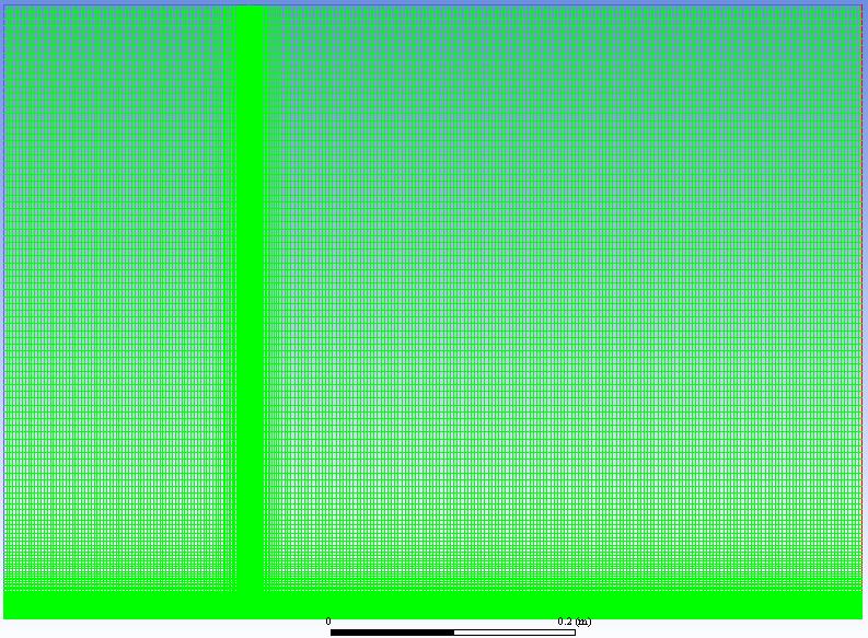
One of the main criteria of getting in-depth CFD analysis correcting is creating the correct mesh. A correct mesh consists of using proper number of cells in region where high fidelity of results is required. The mesh has to be fine enough that the results at the location do not change with mesh size i.e., mesh convergence has occurred at the place in respect to various quantities such as velocity, pressure, etc. To identify the quality of the mesh, various parameters are used aspect ratio, Jacobian ratio, Skewness angle, warping factor and various others to determine whether the mesh created for the problem is sufficient for capturing the physics required.
Choosing the proper solver and scheme
Every commercial software comes with many solvers and schemes which makes it difficult to decide on which solver or scheme to use. Depending on whether the flow considered is compressible or incompressible, either a pressure based or density-based solver are used for performing the CFD analysis. This is important to decide since according to the solver, the physics for the simulation are captured and accordingly the equations used for capturing the quantities change. Furthermore, based on the type of physics to capture, either laminar solver or turbulent solver are used for the simulation. Turbulent solvers such as k-epsilon or Spalart Almaras are selected based on the stability of the model in capturing the CFD analysis to be done in the CFD domain.
The selection of schemes for various quantities such as pressure, momentum, turbulence viscosity is next in line to capture these quantities accurately over the CFD domain. Depending on the accuracy and stability of the analysis required, either a first order, second order or third order scheme is selected for performing the CFD analysis. The higher the order of the scheme, the more accurate the value of the results. However, the disadvantage of using higher order schemes is that the solution becomes unstable and needs more time for performing the complete simulation. Hence a good grid and timestep is required to ensure that higher order schemes are stable and provide accurate results for the simulation.
Choosing whether steady or unsteady analysis
Based on the whether the results are required when the flow variables are changing with time or constant, the CFD analysis can be separated in two parts: Steady flow analysis and Transient flow analysis. Steady flow analysis is provided by CFD analysis services to clients when the flow is assumed to be laminar and the client is interested in understanding the ideal case scenario in the design. The steady flow analysis services are especially useful when the size or shape of the cross section does not change much and the client is interested in finding whether is there any localized effect of the flow in the design.
Transient flow analysis is provided by CFD analysis services to clients when it is important to capture the comprehensive data on time varying flow features or phenomenon and understand the effect of time on the overall design of the product. The transient flow analysis services are especially useful to clients when there is dynamic movement of parts in the design which influence the movement of the flow.
Validation and Verification
Once the CFD analysis is done, it is important to verify or validate the CFD results with either results available in literature or with experimental results. It is important that sufficient time be spent in making sure the results obtained are useful and accurate enough to be compared with results or trends obtained in the literature. For validation, the quantities such as velocity, pressure, temperature at particular key locations and the values of these quantities are compared with the results from experiment or literature. The accuracy percentage is calculated based on the difference between the two results. The results are expected to be lesser than 5 percent. There are various online repositories also which provide results to verify and validate the solver and scheme capabilities that are used for the CFD domain.
Postprocessing and Interpretation

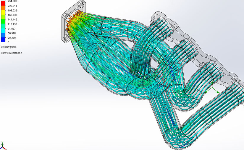
The last part in getting the in-depth CFD analysis done is performing postprocessing analysis of the results obtained. It is important to analyze and understand the various CFD results that are obtained after the analysis. Based on analyzing various quantities such as contours, 3D streamlines and various X-Y plots, the results are analyzed and interpreted to give complete information of the results obtained in the simulated conditions. These results are then converted into insights and design decisions by various CFD companies which either propose design changes or solutions to optimize based on the requirement of the client. Based on the process discussed above, this is how one can get a complete in-depth CFD analysis done.